If you’ve ever picked up a polyethylene bag and noticed subtle thick-thin bands running across its surface, you’ve glimpsed one of the most persistent headaches in plastics manufacturing. Gauge variation—uneven film thickness—is a silent profit killer. It leads to overweight rolls, print registration problems, and complaints from converters who expect consistency down to the micron. But gauge variation isn’t a material defect; it’s a process signature. And once you learn to read that signature, you can do something about it.
The blown film extrusion line is deceptively simple from the outside: resin goes in one end, a bubble rises, and a roll of film emerges at the other. Inside that bubble, though, is a ballet of rheology, thermodynamics, and airflow that demands rigorous control. Whether you’re running monolayer grocery sacks or a 9-layer barrier film for food packaging, understanding the fundamentals is what separates a struggling line from a profitable one. In this guide, we’ll walk through every major stage of the process—and point out the improvement levers most operators overlook.
1. The Feed Zone: More Than Just Dumping Pellets
Everything downstream depends on what happens before the screw even begins to melt. Inconsistent blends of virgin, regrind, and masterbatch can cause surging, where the extruder output fluctuates rhythmically, creating thick and thin bands in the final film. The root cause is often simple: static separation in the hopper or irregular particle size between components.
A best practice that high-efficiency operations adopt is gravimetric blending paired with continuous mass flow monitoring. Rather than relying on volumetric dosing, gravimetric systems measure actual weight per component and adjust in real time. This stabilizes the melt pressure at the die entry—a prerequisite for tight gauge control. If you’ve been chasing gauge variation without first examining your feed consistency, you may be solving the wrong problem.
2. The Extruder: Where Thermodynamics Meets Shear
The single-screw extruder remains the workhorse of blown film, yet its simplicity hides complexity. Three zones—feed, compression, and metering—must be profiled correctly for each resin family. A common mistake is running the feed throat too cold, which leads to premature melting and poor solids conveying, ultimately limiting throughput.
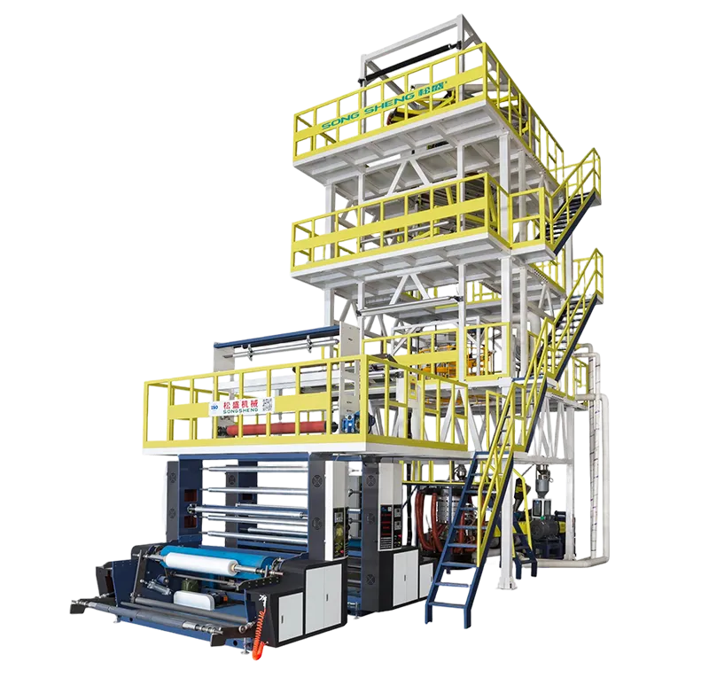
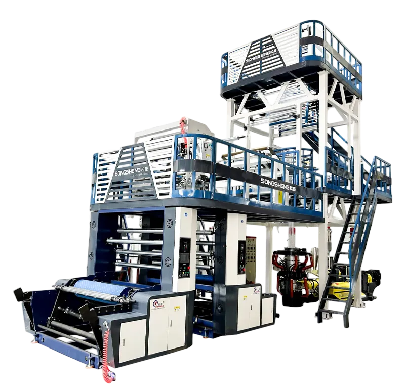
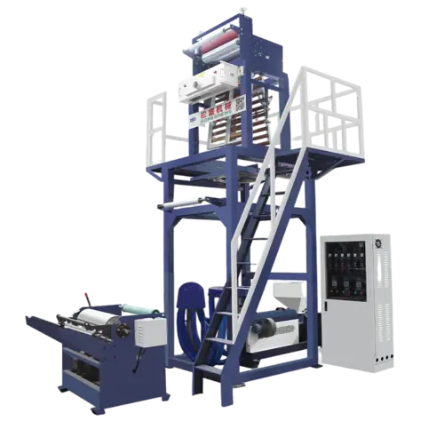
Barrier screws have become the standard for high-output lines, particularly when running LLDPE-rich blends. They separate the solid bed from the melt pool, improving homogenization and reducing the risk of unmelted gels reaching the die. For converters considering an upgrade, moving from a general-purpose screw to a barrier design can unlock an extra 15–25% in throughput without increasing the drive load—a change that pays for itself within months. If you’re evaluating such an upgrade, an efficient blown film production line designed for high-output LLDPE blends can offer the screw geometry and temperature control needed to maintain melt quality at speed.
3. The Die: The Heart of the Bubble
If the extruder is the lungs, the die is the heart. Here, the melt is distributed into a thin, continuous annulus that becomes the film. Spiral mandrel dies dominate the industry because they eliminate knit lines—the weak spots that plague older crosshead dies. However, the design of the spiral channels directly affects residence time distribution. Poorly designed mandrels leave some polymer molecules lingering too long, degrading and forming black specks that ruin roll quality.
Equally critical is the die gap. Typical gaps range from 0.8 to 2.5 mm, with tighter gaps favoring better melt strength utilization and higher draw-down ratios. But a gap that’s too tight can raise backpressure excessively, limiting output or even causing melt fracture. Melt fracture appears as a rough, "shark-skin" surface on the film and is often misdiagnosed as contamination. The fix is usually a combination of die gap adjustment, temperature profiling, and sometimes a processing aid additive—not necessarily a hardware replacement.
4. Cooling and Stabilization: The Science of the Air Ring
Once the melt exits the die, it enters the critical bubble formation zone. The difference between a line running at 200 kg/h and one struggling at 140 kg/h often lies not in the extruder, but in the cooling configuration. Single-lip air rings are adequate for lower outputs, but dual-lip air rings, with their dedicated pre-cooling and main cooling streams, dramatically improve bubble stability and heat transfer rates.
Internal Bubble Cooling (IBC) takes this further by introducing chilled air inside the bubble, nearly doubling the available cooling surface area. In fact, data from multiple processing studies shows that IBC can increase output by 20–35% for a given die diameter, while simultaneously reducing gauge variation by tightening the freeze line height stability. The freeze line, where the molten film solidifies from transparent to hazy, should sit level and steady. Any oscillation here telegraphs directly into thickness variation downstream. If you’re serious about pushing maximum output with minimal variation, a cooling system that integrates dual-lip air rings with advanced IBC controls is worth a close look.
5. The Bubble Cage and Collapsing Frame: Geometry Matters
Between the freeze line and the nip rolls, the bubble must be guided and flattened without inducing wrinkles or shifting the web. An iris-controlled bubble cage with adjustable wooden or composite slats maintains the bubble’s diameter and aligns it centrally. The collapsing frame, typically a trapezoidal arrangement of rollers, converts the round bubble into a flat lay-flat. This is where edge folds—another frequent defect—originate if the geometry is off or the rollers aren’t perfectly tangent to the film surface.
A parameter often overlooked is the collapsing ratio: the length from freeze line to nip rolls relative to bubble diameter. Too short a collapsing frame introduces excessive strain in the film’s edges, leading to splitty rolls and poor converting performance later. A well-designed collapsing system keeps the web tension uniform across the full width, protecting the gauge profile you’ve worked hard to achieve earlier in the line.
6. Winding: The Final Arbitrator of Quality
A winder that jerks or oscillates can ruin film that was flawless up to the nip. Gap winding, where the roll is driven by a center shaft and the film is laid on without nip pressure, is preferred for tacky or very thin films. Contact winding, with a lay-on roller, works well for thicker films but demands precise tension taper programming. As the roll builds in diameter, tension must decrease to avoid starring (wrinkling at the core) or telescoping (roll edges sliding out).
Modern winders feature automatic cut-over and transfer to fresh cores at full line speed, minimizing downtime and scrap. If your operators dread roll changes because of the manual threading hassle or frequent web breaks, the winder design, not the operator skill, is often the limiting factor.
Common Troubleshooting Patterns
Let’s connect the dots with a few real-world patterns:
-
Symptom: Gauge variation exactly 4 times per circumference of the lay-flat. Likely cause: Die lip misalignment or uneven air gap. Check die centering and air ring concentricity.
-
Symptom: Periodic transverse bands of haze every few metres. Likely cause: Melt pressure surging traced back to a worn screw feed zone or an inconsistent blend of regrind. Verify gravimetric system calibration.
-
Symptom: "Chevron" wrinkles near the edges of the roll. Likely cause: The collapsing frame rollers are not parallel, creating a tension bias that pulls one edge tighter than the center.
These diagnostic patterns come from years of line audits and process studies. In each case, the root cause wasn’t a mystery—it was a measurable deviation from established process norms. ASTM D882 for film tensile properties and ISO 1183 for density verification often serve as the backdrop for benchmarking film quality, but the daily operational metrics—output rate, scrap percentage, and gauge profile standard deviation—are the numbers that determine profitability.
When It’s Time to Look Beyond Incremental Adjustments
Process optimization can solve many problems, but there comes a point where the hardware itself becomes the bottleneck. An extruder with a worn barrel, a die that can’t hold thermal uniformity, or a winder that limits line speed are not process issues—they’re investment decisions.
This is where thinking shifts from "fixing" to "upgrading." And in today’s market, even modest improvements in output per kWh or scrap reduction can swing a business case. Some processors find that moving to a larger die diameter with advanced IBC and automated gauge control reduces material waste by 2–4% while boosting throughput—payback periods under 18 months are not uncommon.
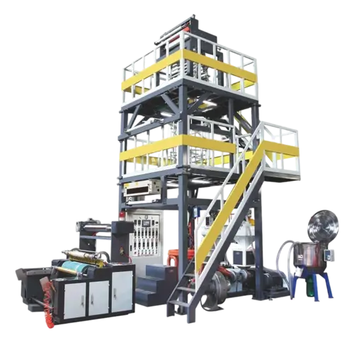
If you’re considering a step change rather than incremental tinkering, Songsheng’s production solutions for multi-layer and high-output film applications are engineered around this exact concept: that the line should work for the process, not the other way around. You can explore configurations tailored to your specific resin blend, layer structure, and output target.
A Note on Data-Driven Decision Making
One final thought: the best film producers are not necessarily the ones with the newest equipment. They are the ones who measure systematically, document their process settings religiously, and train operators to understand cause-and-effect rather than to just press buttons. The technology is an enabler. A line that logs die temperature profiles, motor loads, and gauge measurements every second gives you a treasure trove of data to analyze trends. When combined with a disciplined approach to maintenance—checking heater bands, cleaning air ring lips, and calibrating load cells on schedule—this data approach dramatically extends the life of capital equipment.
For readers who want to dig deeper into material rheology and its impact on film properties, the annual ANTEC conference proceedings and publications from the Society of Plastics Engineers offer peer-reviewed research that can inform your process development.
References & Further Reading
-
ISO 1183-1:2019, Plastics — Methods for determining the density of non-cellular plastics
-
ASTM D882-18, Standard Test Method for Tensile Properties of Thin Plastic Sheeting
-
Giles, H. F., Wagner, J. R., & Mount, E. M. (2005). Extrusion: The Definitive Processing Guide and Handbook. William Andrew.
Disclaimer: Process recommendations are general in nature. Equipment specifications, resin behavior, and safety protocols must be verified with manufacturers and qualified engineers before implementation.