English
 Español
It usually starts with a subtle change—a faint wobble in the bubble, a barely visible line running through the roll, a slight rasp in the layflat. Then scrap rates climb. A rushed die-lip adjustment returns for two shifts, only to reappear worse than before. One production manager we spoke to described the experience as “chasing ghosts in the melt.”
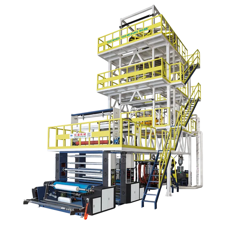
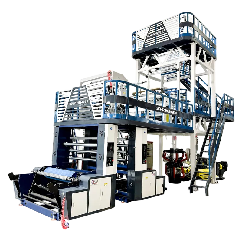
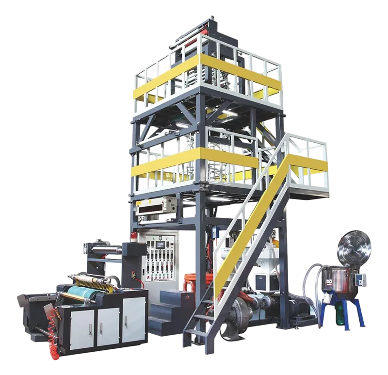
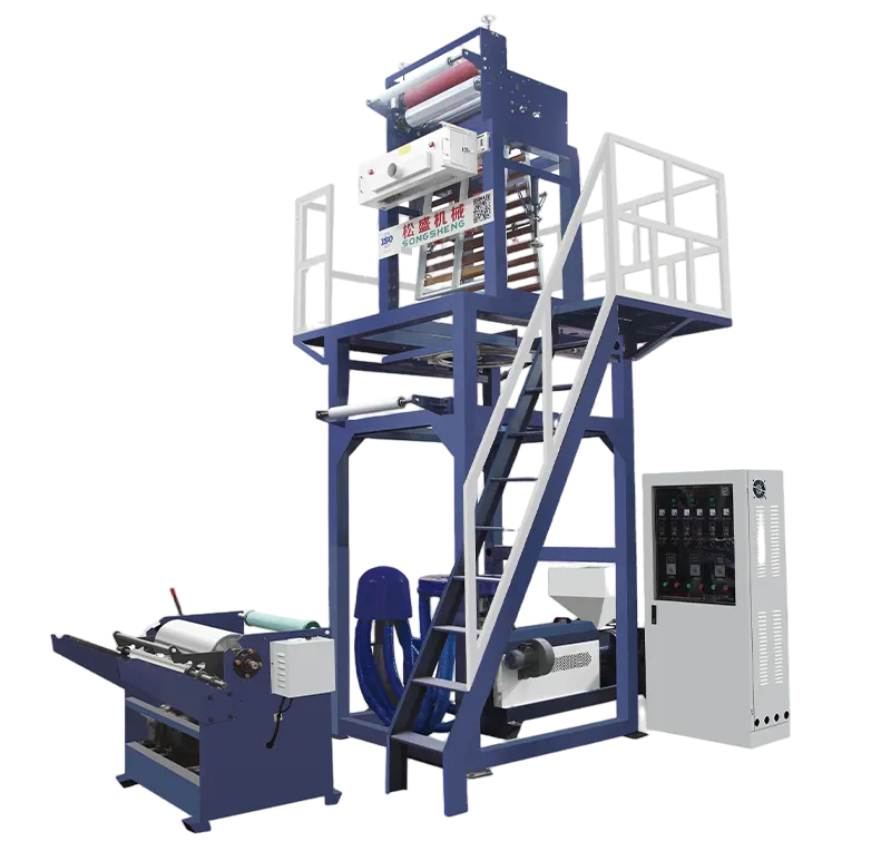
The frustration is real because the costs are immediate: kilograms of off-spec film, lost machine hours, delayed shipments. Yet most common blown film defects follow a handful of patterns. Once you recognize what the film is telling you, the fixes become systematic rather than mysterious. And sometimes, identifying the root cause also tells you whether the real solution is a process adjustment or moving to a more capable extrusion platform. For teams evaluating whether their current setup is holding them back, modular extrusion systems engineered for multi-layer flexible packaging can make a measurable difference in defect rates and output consistency.
Below are five defects almost every blown film operator encounters, along with the most frequent causes and practical countermeasures.
1. Bubble Instability (Hunting or Breathing)
What you see: The frost line height oscillates by more than a few centimeters, or the bubble sways left to right even in still air. Gauge control becomes erratic, and roll formation suffers.
Most common causes:
-
Uneven airflow from the air ring, often due to partially clogged lips or an unbalanced air supply.
-
Drafts in the production hall—overhead doors left open, nearby cooling fans, even pedestrian traffic patterns that create unpredictable air currents.
-
Melt temperature swings exceeding 3–5°C at the die, typically from worn heater bands or a poorly tuned temperature controller.
Practical fixes:
Begin by thoroughly cleaning the air ring lips with a brass tool—never steel, which can nick the surface and create permanent airflow streaks. Verify that the air ring is centered to the die within the manufacturer’s tolerance, usually under 0.5 mm total indicated runout. If the bubble still hunts, check for ambient drafts using a smoke stick or a length of surveyor’s tape; simple PVC strip curtains around the tower often solve the problem at negligible cost. Document the frost line height with a fixed scale on the tower so operators have an objective reference rather than relying on feel. According to the *TAPPI TIS 0808-04* guideline on blown film stability, maintaining consistent cooling air temperature—within ±2°C of the setpoint—can reduce bubble diameter variation by as much as 40%.
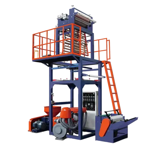
2. Melt Fracture (Sharkskin or Orange Peel)
What you see: A rough, matte surface texture, especially at higher output rates. In severe cases, the film surface looks like fine sandpaper; in mild cases, it loses gloss and transparency.
Most common causes:
-
Excessive shear stress at the die lip exit, often because the polymer is being pushed through too cold or through a die gap that is too narrow for the resin’s molecular weight distribution.
-
Insufficient die lip temperature—usually 10–15°C below the recommended processing window for the specific grade of LLDPE or mLLDPE.
-
Contamination or degraded material building up at the die lip exit, creating a micro-roughness that initiates the fracture pattern.
Practical fixes:
First, raise the die temperature in 5°C increments and observe for improvement; many sharkskin issues on LLDPE disappear once the die lip temperature reaches 200–215°C. If the problem persists, widen the die gap slightly—a change of 0.1 mm can reduce exit shear stress significantly without altering final film gauge, as the blow-up ratio and haul-off speed will compensate. For extrusion lines that frequently run high-viscosity specialty resins, precision extrusion equipment with optimized melt-channel geometry eliminates many of the dead spots that cause material degradation, which is particularly important when processing heat-sensitive barrier polymers.
It’s also worth examining your purge routine. A large-scale survey of 120 blown film operations published by Plastics Technology found that lines performing a dedicated die-lip purge at every resin changeover reported 60% fewer melt fracture events than those relying solely on the extruder screw to clear previous material.
3. Gauge Variation (Thick and Thin Bands)
What you see: Bands of thicker and thinner film running in the machine direction, visible as uneven transparency or, when the roll is slit, as obvious hard and soft spots in the layflat. Some operators call it "piston ring" effect.
Most common causes:
-
Non-uniform die gap around the circumference. Even a misalignment of 0.02–0.05 mm creates measurable gauge bands.
-
Uneven melt temperature distribution arriving at the die, often due to a worn screw or improper screw design for the resin being run.
-
Inadequate or unbalanced air ring cooling causing differential shrinkage around the bubble circumference.
Practical fixes:
Begin with a cold die-gap check using a feeler gauge at a minimum of eight equally spaced points around the die circumference. Adjust per the die manufacturer’s procedure; many modern dies have a centering mechanism that can be corrected without removing the die. If the mechanical gap is uniform, the next step is to profile the melt temperature as it exits the die using a fast-response thermocouple probe—a difference of more than 4°C across quadrants points to poor melt homogeneity upstream, requiring evaluation of the screw and barrel condition. Processing conditions also matter: an incorrect blow-up ratio (BUR) can amplify minor gauge variation into a visible defect. For general-purpose films, maintaining a BUR between 2.0:1 and 3.0:1 is a safe starting point, though this should be verified against the resin supplier’s datasheet.
4. Film Wrinkling in the Nip or Layflat
What you see: Wrinkles appearing as the bubble collapses into the nip rolls, often concentrated near the edges or as a single persistent crease traveling through the layflat.
Most common causes:
-
Misaligned collapsing frame relative to the die center. Even a 1–2 mm offset causes asymmetric tension that folds the film before it reaches the nip.
-
Nip roll pressure imbalance from left to right, or worn rubber roll covers with flat spots or hardness variation.
-
Excessive collapsing-frame friction, especially with sticky film structures such as EVA-based formulations.
Practical fixes:
Use a plumb line dropped from the exact center of the nip to verify the collapsing frame and die are on a common vertical axis. Check the A-frame or side-guide rollers for free rotation—sticky bearings are a frequently overlooked cause. Set the nip pressure using load cells if available, or with a standardized footprint test to verify uniform contact across the full roll width. For sticky films, consider colloidal-silica-treated roller surfaces or air-assisted turning bars to reduce contact drag. These adjustments become easier to maintain when the entire tower assembly is built to minimize misalignment drift over time. For operations wanting to upgrade without a full plant overhaul, exploring robust film take-off and winding configurations can point to integrated solutions that hold alignment better across long production runs.

5. Gels and Fisheyes
What you see: Small, hard, translucent or colored specks embedded in the film, often surrounded by a slight distortion ring. They create weak points and ruin printability.
Most common causes:
-
Unmelted resin particles, often from cross-contamination of a higher-melting-point polymer in the feedstock or from poor screw design that leaves some pellets unmelted.
-
Thermally degraded material that has sat too long in dead spots inside the die, adapter, or screw flights, breaking down into oxidized gel particles.
-
Incompatible reprocessed material with a different melt history that does not homogeneously blend into the virgin melt stream.
Practical fixes:
Install a screen pack with a finer mesh—moving from a 60/100/60 pack to an 80/120/80 arrangement can trap gels before they reach the die, though at the cost of some backpressure which must be evaluated against the extruder’s capability. Purge the system thoroughly according to a written procedure that specifies the time and target melt temperature for each zone; shortcutting this step often re-introduces the same degraded material that caused the issue. If gels persist after purging and re-screening, examine the screw and barrel for signs of wear or pitting in the compression zone, which create low-velocity regions where resin can stagnate. This is one area where the inherent design of the melt pathway matters a great deal. Equipment built with streamlined, crevice-free flow channels and polished internal surfaces helps prevent the hang-ups that generate gels—something worth examining if gel problems have become chronic despite your best housekeeping.
Building Consistency Into the Process
Troubleshooting blown film defects is a mix of disciplined observation and methodical elimination of variables. The best operators I’ve seen keep a simple defect log at the line—just a date, resin lot, temperature profile, and a small tape sample of the defect. Over weeks, patterns emerge that no single shift would catch.
That said, even the most skilled operator will struggle if the underlying equipment is working against them—through uneven cooling, drift-prone alignment, or melt-channel geometry that penalizes certain resin families. When the fixes described above become a recurring routine rather than an occasional intervention, it may be time to step back and consider whether the asset itself is reaching the limit of its capability.
If you’re aiming for a more repeatable process and fewer fire-fighting weekends, it’s worth taking a look at how modern film extrusion lines are being designed specifically to address these day-to-day defect drivers. Songsheng’s blown film extrusion platforms, for instance, focus on tight thermal uniformity, balanced air-ring dynamics, and simplified maintenance access—features that directly support the kind of process discipline discussed above. Get a closer look at Songsheng’s film extrusion solutions and available configurations to see what would fit your production environment.
Disclaimer: This article provides general troubleshooting guidance. Actual processing conditions depend on specific resin grades, machine configurations, and plant conditions. Always consult your material supplier’s processing guide and your equipment manufacturer’s recommendations before making significant process changes.