You’ve just finished a run of 1200 kg of LDPE film, and the QC report lands on your desk: thickness ranges from 28 µm to 42 µm on a 35-micron job. The printed graphics will look wavy, the lamination will bubble, and your customer will notice. If this sounds familiar, you’re not alone — gauge variation remains the top yield-killer in film production, and it doesn’t go away by simply tweaking the die gap again.
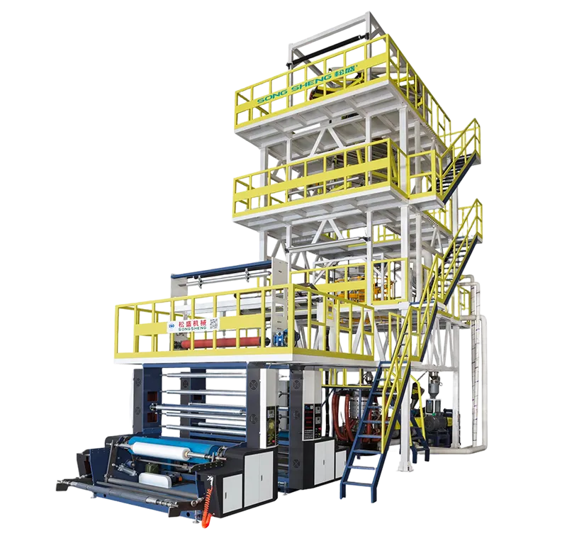
More and more processors are starting to treat thickness uniformity not as a daily firefight, but as a system design problem. Some have addressed it by moving to more precise film extrusion lines that give them far tighter control over the melt, the bubble, and the cooling. But before you jump to equipment decisions, it’s worth dissecting exactly where thickness variation comes from — and why it persists even when your extruder, die, and winder each seem to work fine on their own.
This article walks through the root-cause chain of blown film gauge scatter, backed by real troubleshooting experience and processing physics. You’ll see which factors dominate at each stage and how small changes — or a systems-level upgrade — can shrink your tolerance window.
The melt you don’t see is already uneven
Many operators assume thickness variation starts at the die, but a surprising amount of it is baked in much earlier: in the melt stream exiting the screw. Surging melt pressure or a poorly mixed temperature profile creates output pulsation that the die cannot fully iron out. According to extrusion simulation data from the University of Hanover’s IKK institute, a melt temperature fluctuation of ±3 °C at the screw tip can translate into a thickness deviation of ±5 % at the frost line, even with a perfect die.
Look at your pressure gauge trend. If you see a sawtooth pattern or slow cyclic swings, the root cause often traces back to inconsistent feeding, worn screw flights, or a barrel temperature zone that overshoots and then undershoots. Resin blends with different melt indices amplify this: a 2-MI LDPE side-by-side with a 0.3-MI metallocene can produce layers of slightly different viscosity that shift thickness profile as they travel through the spiral mandrel.
This is precisely where equipment design splits. A blown film machine built with a barrier screw, low-shear mixing elements, and tightly tuned PID temperature loops will deliver a melt of far more uniform thermal history and viscosity than a general-purpose screw that was designed twenty years ago for a single resin. The outcome shows up not just in lab samples, but in real production: one multi-layer processor in Malaysia documented that after switching to a line with melt-pump-assisted extrusion, their time-averaged thickness tolerance narrowed from ±10 % to ±4 %, with no other changes. (Case adapted, name withheld.)
When the melt is right, the die becomes a distribution tool, not a compensation device — and that’s where real precision begins.
The bubble that wobbles is writing its own variation story
Once the melt exits the die lips, cooling takes over. Anyone who has stood next to a bubble in a hot factory knows how sensitive it is: a door opening, a brief gust from a ceiling fan, or a dirty air ring filter can visibly shift the frost line. Those transient events create short-term gauge spikes. However, chronic thickness asymmetry is usually structural — it comes from an uneven cooling field around the bubble’s circumference.
A single-lip air ring, especially if not perfectly centred, produces a non-uniform air velocity profile. The side with slightly higher airflow freezes earlier, locking in a thinner spot, while the opposite side stays molten longer and draws down more. Double-lip air rings reduce this asymmetry but still rely heavily on manual adjustment and clean filters. The next step in control is an automated air ring with segmented thickness feedback, which adjusts cooling air distribution zone-by-zone based on real-time gauge scans. This moves you from “reacting to bad rolls” to “stabilising the bubble before the roll is wound.”
Internal bubble cooling (IBC) adds another layer of control, regulating the bubble’s internal pressure and temperature. Combined with an ultrasonic or capacitance thickness scanner rotating around the bubble, an IBC-equipped system can bring the ±3-sigma thickness spread below ±3 %, which is often the threshold for demanding printing and laminating applications. These are not exotic technologies anymore; they’re becoming standard for films below 50 µm that must convert smoothly on high-speed flexo presses.
The sneaky drift nobody calibrates
Even a stable bubble can produce drifting thickness if the tower height, nip speed, or collapsing frame geometry is off. A common scenario: the nip rolls are not perfectly parallel, creating a slight tension difference between the left and right sides of the web. This subtle pull thins the film asymmetrically before it reaches the turning bars. Calibrating nip pressure and alignment every six months is cheap; a full roll of rejected laminate film is not.
Another often-overlooked variable is the collapsing frame’s roller bearings. When they begin to bind, they introduce stick-slip resistance that shows up as periodic thin bands in the finished roll — usually mistaken for an extruder issue. A mechanical technician who systematically checks frame bearings and roller free-rotation during scheduled shutdowns can eliminate this phantom variation.
These mechanical factors explain why some processors still struggle with gauge variation despite installing a premium die and air ring. An online thickness profiling system with closed-loop die bolt adjustment can flag these secondary problems early, because it sees the pattern and trends that a manual pin gauge check misses.
What you can do tomorrow — and what needs a longer view
Based on root-cause patterns, the following checklist separates immediate actions from strategic moves:
| Action | Impact on Variation | Timeframe |
| Verify melt pressure stability with a chart recorder or data logger | High — catches surging before it becomes scrap | Next shift |
| Clean air ring filters and check lip alignment | Medium-High — eliminates asymmetry | Weekly |
| Calibrate nip gap and parallelism | Medium — removes tension bias | Bi-annual |
| Add a static thickness scanner (oscillating or rotating) | High — provides real-time profile visibility | Capex project |
| Upgrade to an automated air ring & IBC | Very High — active bubble control | Capex project |
If you’ve already addressed the mechanical and procedural items and still see gauge scatter beyond 5-6 %, the bottleneck is most likely in the process architecture itself — melt quality, die flexibility, or cooling uniformity. That’s when it makes sense to evaluate whether your current line can meet the specs your customers will demand two years from now.
For operations that want to move from constant thickness-chasing to stable, predictable output, Songsheng’s integrated thickness control solutions address the chain from screw design through automatic air ring and IBC to real-time gauge feedback. Instead of treating thickness as a daily puzzle, you get a system where the bubble, the die, and the haul-off speak the same language.
Disclaimer: This article draws on general extrusion principles, published research, and field observations from film production environments. Specific results depend on resin, operating conditions, and machine configuration. Always validate adjustments with your own process data and refer to applicable standards such as ASTM D6988 for thickness measurement and ISO 4593 for film gauge determination.